Foram encontradas 433 questões
Resolva questões gratuitamente!
Junte-se a mais de 4 milhões de concurseiros!
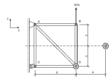
A figura mostra uma estrutura composta pelas barras AB, AC, AD e CD e BD articuladas em suas extremidades. O apoio no ponto A impede os deslocamentos nas direções x e y, enquanto o apoio no ponto C impede o deslocamento apenas na direção x. No ponto D dessa estrutura encontra-se uma partícula elétrica de carga positiva q. Uma partícula elétrica de carga positiva Q encontra-se posicionada no ponto indicado na figura. Uma força de 10 N é aplicada no ponto B, conforme indicada na figura. Para que a força de reação no ponto C seja zero, o produto q.Q deve ser igual a:
Observação: • as barras e partículas possuem massa desprezível; e • as distâncias nos desenhos estão representadas em metros.
Dado: • constante eletrostática do meio: k.
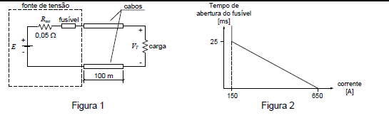
Uma fonte de tensão com tensão interna E e resistência interna Rint = 0,05 Ω, protegida por um fusível, alimenta uma carga por meio de dois cabos com resistência linear igual a 1 Ω/km, como mostra a Figura 1. A Figura 2 mostra a aproximação da reta característica de operação do fusível utilizado na fonte.
Inicialmente, a carga que consome 10 kW e opera com tensão terminal VT igual a 100 V, mas, subitamente, um curto circuito entre os cabos que alimentam a carga faz com que o fusível se rompa, abrindo o circuito.
Sabendo-se que o tempo de abertura do fusível foi de 1,25 ms, a energia total dissipada nos cabos, em
joules, durante o período de ocorrência do curto circuito é, aproximadamente:
 , o raio da Terra obtido por meio
desse experimento é
, o raio da Terra obtido por meio
desse experimento é Observações: • considere a terra uma esfera perfeita; • considere o eixo de rotação do planeta perpendicular ao plano de translação; • o experimento foi executado na linha do Equador; e • desconsidere o movimento de translação da Terra.
Dados: • período de rotação da Terra: T; e • distância vertical entre os olhos do segundo observador e o nível do mar: ℎ
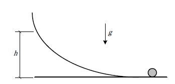
Um cilindro de raio R rola, sem deslizar, em velocidade angular  , sobre uma superfície plana horizontal
até atingir uma rampa. Considerando também que o rolamento na rampa seja sem deslizamento e
chamando de g a aceleração da gravidade, a altura máxima, h, que o eixo do cilindro alcança na rampa
em relação à superfície plana é:
, sobre uma superfície plana horizontal
até atingir uma rampa. Considerando também que o rolamento na rampa seja sem deslizamento e
chamando de g a aceleração da gravidade, a altura máxima, h, que o eixo do cilindro alcança na rampa
em relação à superfície plana é:
Dados: • diâmetro do tubo à esquerda: 20 mm; • diâmetro do tubo à direita: 10 mm; e • densidade do fluido: 1,2.
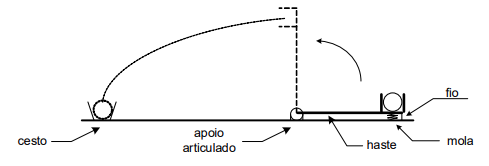
A figura mostra uma haste de massa desprezível com um apoio articulado em uma extremidade. A outra extremidade possui um recipiente apoiado em uma mola e amarrado ao solo por um fio. A haste é mantida na posição horizontal e a mola comprimida. Uma bola é colocada nesse recipiente e, após o corte do fio, o sistema é liberado com distensão instantânea da mola.
A constante elástica da mola, em N/m, para que, quando a prancha estiver perpendicular ao solo, a bola seja lançada e acerte o cesto é:
Dados:
• comprimento da prancha: 1 m;
• distância do apoio ao cesto: 5 m;
• massa da bola: 200 g;
• deformação inicial da mola: 10 cm; e
• aceleração da gravidade: 10 m/s2
Observação:
• despreze as dimensões da bola.
Calor específico – [c] Coeficiente de dilatação térmica – [a] Constante eletrostática – [k] Permeabilidade magnética – [u]
A alternativa que expressa uma grandeza adimensional é:
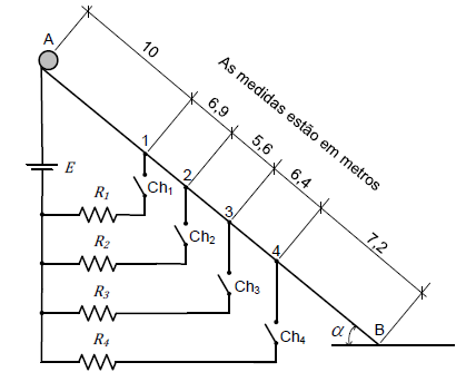
Dados: • R1 = 10 Ω; • R2 = 10 Ω; • R3 = 5 Ω; • R4 = 2,5 Ω; • E = 10 V; • a= 30º; e • g = 10 m/s
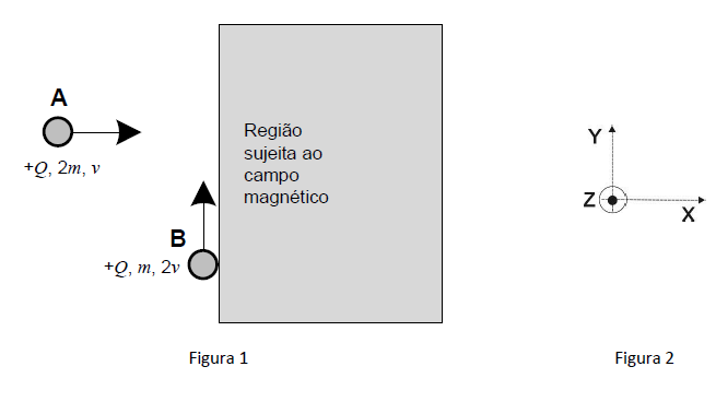
Duas partículas A e B, ambas com carga positiva +Q e massas 2m e m, respectivamente, viajam, em velocidades constantes v e 2v e nas direções e sentidos mostrados na Figura 1, até se chocarem e ficarem grudadas no instante em que penetram numa região sujeita a um campo magnético constante ( 0 , 0 , B ), sendo B uma constante positiva. O comprimento da trajetória percorrida pelo conjunto A+B dentro da região sujeita ao campo magnético é:
Observações: • despreze o efeito gravitacional; • antes do choque, a partícula B viaja tangenciando a região sujeita ao campo magnético; • o sistema de eixo adotado é o mostrado na Figura 2; e • despreze a interação elétrica entre as partículas A e B.
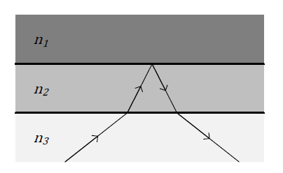
A figura acima mostra três meios transparentes, de índices de refração n1, n2 e n3, e o percurso de um raio luminoso. Observando a figura, é possível concluir que:
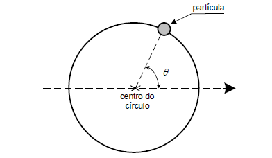
Uma partícula desloca-se solidária a um trilho circular com 0,5 m de raio. Sabe-se que o ângulo q, indicado na figura, segue a equação q = t 2 , onde t é o tempo em segundos e q é o ângulo em radianos. O módulo do vetor aceleração da partícula, em t = 1 s, é:
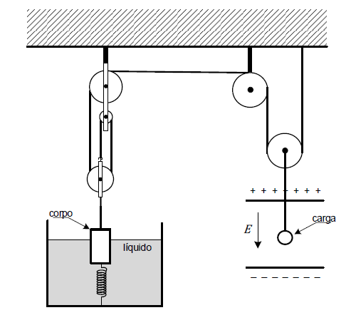
Dados: • a corda e as roldanas são ideais; • aceleração da gravidade: g • massa específica do fluido: p; • massa específica do corpo: 2p; • constante elástica da mola: k; • volume do corpo: v; • intensidade do campo elétrico uniforme: E; • massa da carga elétrica: m; e • carga elétrica: + q.
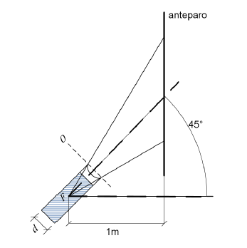
Uma lanterna cilíndrica muito potente possui uma lente divergente em sua extremidade. Ela projeta uma luz sobre um anteparo vertical. O eixo central da lanterna e o eixo principal da lente estão alinhados e formam um ângulo de 45º com a horizontal. A lâmpada da lanterna gera raios de luz paralelos, que encontram a lente divergente, formando um feixe cônico de luz na sua saída. O centro óptico da lente 0 está, aproximadamente, alinhado com as bordas frontais da lanterna. A distância horizontal entre o foco F da lente e o anteparo é de 1 m. Sabendo disto, pode-se observar que o contorno da luz projetada pela lanterna no anteparo forma uma seção plana cônica. Diante do exposto, o comprimento do semieixo maior do contorno dessa seção, em metros, é:
Dados:
• a lente é do tipo plano-côncava; • a face côncava está na parte mais externa da lanterna; • diâmetro da lanterna: d = 10 cm; • índice de refração do meio externo (ar): 1; • índice de refração da lente: 1,5; • raio de curvatura da face côncava: 2,5 √3 cm.
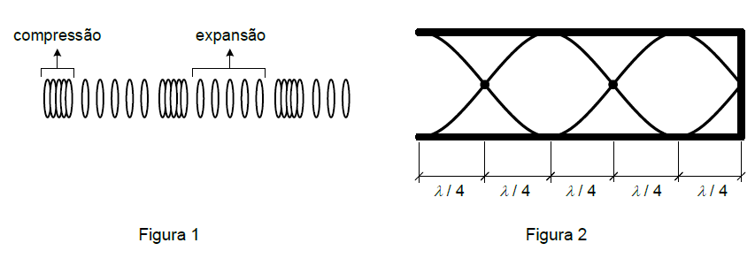
Considerando as Figuras 1 e 2 acima e, com relação às ondas sonoras em tubos, avalie as afirmações a seguir:
Afirmação I. as ondas sonoras são ondas mecânicas, longitudinais, que necessitam de um meio material para se propagarem, como representado na Figura 1.
Afirmação II. uma onda sonora propagando-se em um tubo sonoro movimenta as partículas do ar no seu interior na direção transversal, como representado na Figura 2.
Afirmação III. os tubos sonoros com uma extremidade fechada, como representado na Figura 2, podem estabelecer todos os harmônicos da frequência fundamental.
É correto o que se afirma em:
Texto 4
FRANK WHITTLE AND THE INVENTION OF THE JET ENGINE:
SIX PLACES TO TRACE HIS GENIUS
It was, in many ways, a very British sort of achievement. When the turbine began to spin on the “WU” – the prototype jet engine developed by the Coventry-born engineer Frank Whittle – it was a moment which changed the world. Had you been passing through the byways of Rugby, in Warwickshire, more than 80 years ago, you might even have heard it. A thrum of mechanics in sync, building and building, growing in intensity to become a roar; a giddy howl which would permanently alter the way we journey around our planet.
And yet it might so easily not have happened. Whittle’s triumph – on April 12, 1937 – was garnered in the face of official indifference and scientific doubt, and was only pulled off by a merest financial hair’s breadth, with the Second World War crowding in on all sides.
( . . . )
Here was a visionary who began fomenting his design for a jet engine as early as 1927, and patented it in 1930, yet had to swim against the current after seeing his idea pooh-poohed by the UK's Air Ministry – which, upon seeing the blueprint in 1929, deemed it “impracticable.”
Undeterred, Whittle took his own path. In January 1936, he founded a private company, Power Jets Ltd, with aeronautical engineer Rolf Dudley Williams and retired RAF officer James Collingwood Tinling. With £2,000 of funding from O.T. Falk & Partners – an investment bank which was known for taking risks – the trio began converting what had been decried as fantasy into reality. That first blur of blades as the WU (Whittle Unit) screamed into life was followed by a series of leaps forward.
The Air Ministry placed its first order for Whittle’s brainwave in January 1940. The first jet-powered British plane took off from RAF Cranwell, Lincolnshire, on May 15, 1941. The rest is so much history.
None of this occurred in isolation. The story of the jet engine can never be told without mentions of Maxime Guillaume, who secured a French patent for a jet engine with a gas turbine in 1921 (no prototype was ever produced as it was beyond the scope of existing technology), and of Hans Von Ohain, who beat Whittle to the punch by building the first fully operational jet engine in 1939 as Germany chased advantages in the global conflict.
( . . . )
RAF = Royal Air Force
LEADBEATER, C. Adaptado de Frank Whittle and the invention of the jet engine: Six places to trace his genius. In: The Telegraph. Disponível em: <https://www.telegraph.co.uk/travel/destinations/europe/unitedkingdom/england/articles/frank-whittle-and-the-birth-of-the-jet-engine/>. Acesso em: 08/06/2018
Choose the correct option.
The sentence: “That first blur of blades as the WU (Whittle Unit) screamed into life was followed by a series of leaps forward” means that
Texto 4
FRANK WHITTLE AND THE INVENTION OF THE JET ENGINE:
SIX PLACES TO TRACE HIS GENIUS
It was, in many ways, a very British sort of achievement. When the turbine began to spin on the “WU” – the prototype jet engine developed by the Coventry-born engineer Frank Whittle – it was a moment which changed the world. Had you been passing through the byways of Rugby, in Warwickshire, more than 80 years ago, you might even have heard it. A thrum of mechanics in sync, building and building, growing in intensity to become a roar; a giddy howl which would permanently alter the way we journey around our planet.
And yet it might so easily not have happened. Whittle’s triumph – on April 12, 1937 – was garnered in the face of official indifference and scientific doubt, and was only pulled off by a merest financial hair’s breadth, with the Second World War crowding in on all sides.
( . . . )
Here was a visionary who began fomenting his design for a jet engine as early as 1927, and patented it in 1930, yet had to swim against the current after seeing his idea pooh-poohed by the UK's Air Ministry – which, upon seeing the blueprint in 1929, deemed it “impracticable.”
Undeterred, Whittle took his own path. In January 1936, he founded a private company, Power Jets Ltd, with aeronautical engineer Rolf Dudley Williams and retired RAF officer James Collingwood Tinling. With £2,000 of funding from O.T. Falk & Partners – an investment bank which was known for taking risks – the trio began converting what had been decried as fantasy into reality. That first blur of blades as the WU (Whittle Unit) screamed into life was followed by a series of leaps forward.
The Air Ministry placed its first order for Whittle’s brainwave in January 1940. The first jet-powered British plane took off from RAF Cranwell, Lincolnshire, on May 15, 1941. The rest is so much history.
None of this occurred in isolation. The story of the jet engine can never be told without mentions of Maxime Guillaume, who secured a French patent for a jet engine with a gas turbine in 1921 (no prototype was ever produced as it was beyond the scope of existing technology), and of Hans Von Ohain, who beat Whittle to the punch by building the first fully operational jet engine in 1939 as Germany chased advantages in the global conflict.
( . . . )
RAF = Royal Air Force
LEADBEATER, C. Adaptado de Frank Whittle and the invention of the jet engine: Six places to trace his genius. In: The Telegraph. Disponível em: <https://www.telegraph.co.uk/travel/destinations/europe/unitedkingdom/england/articles/frank-whittle-and-the-birth-of-the-jet-engine/>. Acesso em: 08/06/2018
Texto 3
THE DISCOVERY OF PENICILLIN—NEW INSIGHTS AFTER MORE THAN 75 YEARS OF CLINICAL USE
ABSTRACT
After just over 75 years of penicillin’s clinical use, the world can see that its impact was immediate and profound. In 1928, a chance event in Alexander Fleming’s London laboratory changed the course of medicine. However, the purification and first clinical use of penicillin would take more than a decade. Unprecedented United States/Great Britain cooperation to produce penicillin was incredibly successful by 1943. This success overshadowed efforts to produce penicillin during World War II in Europe, particularly in the Netherlands. Information about these efforts, available only in the last 10–15 years, provides new insights into the story of the first antibiotic. Researchers in the Netherlands produced penicillin using their own production methods and marketed it in 1946, which eventually increased the penicillin supply and decreased the price. The unusual serendipity involved in the discovery of penicillin demonstrates the difficulties in finding new antibiotics and should remind health professionals to expertly manage these extraordinary medicines.
( . . . )
GAYNES, R. The Discovery of Penicillin—New Insights After More Than 75 Years of Clinical Use. In: Science, 2017. Disponível em: <http://wwwnc.cdc.gov/eid/article/23/5/16-1556_article>. Acesso em: 26/06/2018.
Choose the correct option.
The meaning of the word “serendipity” in the sentence: “The unusual serendipity involved in the discovery of penicillin demonstrates the difficulties in finding new antibiotics (...)” is: